Energy Storage with a Victron Multiplus Inverter
Using the JFK-Enterprise PowerMaster, a Victron Multiplus Inverter, and a LifePo4 Battery, to create a reliable energy storage solution.

Jakob Kaliwoda

This project is powered by the JFK-Enterprise PowerMaster, a powerful and versatile energy management system that allows you to monitor and control your energy usage with ease.
To find out more about the PowerMaster and how it can help you manage your energy needs, visit the JFK-Enterprise PowerMaster website.
 Buy me a coffee
 Project Target
The goal of this project is to create a reliable and efficient energy storage solution using a Victron Multiplus Inverter, a LifePo4 Battery, and the JFK-Enterprise PowerMaster for energy management. This system will allow for seamless integration of renewable energy sources, backup power during outages, and optimized energy usage for a more sustainable lifestyle.
Main System Components
- Victron Multiplus II GX Inverter: Victron Multiplus II GX Inverter
- Felicity LifePo4 Battery: Felicity LifePo4 Battery
- Raspberry Pi 4: Raspberry Pi 4
- Shelly 3EM Pro Energy Meter: Shelly 3EM Pro
Additionally you need the usual installation material: a DC fuse and battery switch sized for the inverter, AC breakers / RCD for the AC-in and AC-out circuits, and LAN cables to a switch.
System Overview
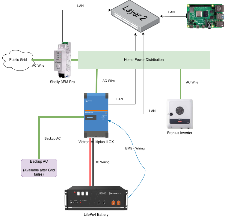
- Public Grid → Shelly 3EM Pro → Home Power Distribution: The Shelly sits directly at the grid connection point and measures the total import/export of the house.
- Home Power Distribution → Multiplus AC-in: The Multiplus is fed from the distribution board like any other consumer and can charge or discharge the battery there.
- Multiplus AC-out → Backup AC: The circuits on AC-out keep running from the battery when the grid fails.
- Fronius Inverter → Home Power Distribution: The existing PV inverter stays on the grid side (AC-in side). Its surplus charges the battery through the Multiplus. During a grid outage the Fronius switches off, so the backup circuits are powered from the battery only.
- Battery ↔ Multiplus: DC wiring (with fuse) plus the BMS communication cable.
- LAN: Shelly, Multiplus II GX, Fronius and the Raspberry Pi are connected to the same network switch.
Step 1: Battery Preparation
- Mount the battery and connect it to the DC terminals of the Multiplus. Use cables with the cross-section recommended in the Multiplus manual, a DC fuse in the positive cable and a battery switch.
- Set the DIP switch of the battery. For a single battery, switches 1 and 5 are ON. When you use several batteries in parallel, the Multiplus must be connected to the first battery (the one with switch 5 ON) – see the Felicity communication guide for the addresses of the other packs.
- Restart the battery – the DIP switch setting is only read at start-up.
Step 2: BMS to Victron Multiplus Connection
The battery reports its state of charge and its charge/discharge limits (CVL, CCL, DCL) to the Victron system via CAN bus. Without this connection the Multiplus does not know how it is allowed to charge the battery, so this cable is essential.
A communication cable is included with the battery. Both ends are RJ45 connectors, but the pinout is not a standard patch cable – a normal LAN cable does not work. If you build the cable yourself, only two wires are needed:
| Pin Victron (BMS-Can) | Pin Battery (CAN) | Function |
|---|---|---|
| 7 | 4 | CAN High |
| 8 | 3 | CAN Low |
Plug the Victron end into the BMS-Can port of the Multiplus II GX and the other end into the CAN port of the battery (not RS485). The CAN bus has to be terminated: if the BMS-Can port has a second socket, put the Victron VE.Can terminator into it.
Step 3: Configuring the Victron Multiplus II GX
All settings below are done on the GX part of the Multiplus via the Remote Console (VRM portal, VictronConnect or the local IP address of the Multiplus in your browser).
Update the firmware
Update the GX to the latest Venus OS version (Settings → Firmware). The native Shelly integration needs at least Venus OS v3.70.
Enable the BMS connection
- Open Settings → Services → VE.Can port (BMS-Can) and set the CAN-bus profile to „CAN-bus BMS LV (500 kbit/s)“.
- After a few seconds the battery appears in the device list with voltage, current and state of charge.
- Open Settings → DVCC and make sure DVCC is enabled and the Felicity battery is selected as BMS. The battery then controls the maximum charge voltage and charge current.
- Under Settings → System setup → Battery monitor select the Felicity battery as battery monitor.
Configure ESS
- Install the ESS Assistant in the Multiplus (VictronConnect or VEConfigure) and select the grid code of your country. Without a grid code the Multiplus does not feed back into the grid.
- In Settings → ESS set the Grid metering to External meter.
- Select the ESS mode. For a battery controlled by the PowerMaster, „Keep batteries charged“ is not used – choose „Optimized (without BatteryLife)“ and set the minimum SOC to the reserve you want to keep for a grid outage.
- Set the Grid setpoint to a small positive value (e.g. 30 W) so the system rather imports a few watts than exporting battery energy.
Add the Shelly 3EM Pro as grid meter
Since Venus OS v3.70 the GX can read Shelly energy meters directly over the LAN. Enable the Shelly integration in the settings, select the Shelly 3EM Pro in the list of found devices and assign the role Grid meter. Check that import from the grid shows as a positive value in the overview – otherwise the current clamps are mounted the wrong way round.
Enable Modbus TCP
The PowerMaster talks to the GX via Modbus TCP. Enable the Modbus TCP server in Settings → Services → Modbus TCP (on newer Venus OS versions under Settings → Integrations). The Venus OS system service listens on port 502 with unit ID 100.
At this point the ESS already works on its own: the Multiplus keeps the grid power around the setpoint, charges the battery with PV surplus and discharges it when the house consumes more than the PV produces.
Step 4: Connecting the JFK-Enterprise PowerMaster
The PowerMaster runs as a container on the Raspberry Pi – see the installation guide. Once it is up, add the devices in the dashboard:
- Victron ESS – adapter Victron ESS (Cerbo GX Modbus), role ESS
- Host: IP address of the Multiplus II GX
- Port:
502, Modbus unit ID:100 - Maximum charge power (W): the hardware limit of your Multiplus/battery
- Optional: maximum discharge power (W) and minimum SOC for discharge – without both values the PowerMaster never tells the ESS to discharge.
- Grid meter – adapter Shelly EM, role Grid, with the IP address of the Shelly 3EM Pro. Enable invert if the meter shows import as a negative value.
- PV – the Fronius inverter, e.g. via the Home Assistant integration or the generic Modbus TCP adapter, role PV.
Use Test connection on every device. The Victron ESS device should report battery power, state of charge and the current ESS set point.
Then create a policy that binds the ESS, the PV inverter(s) and the grid meter, and set the reserve SOC and the maximum PV charge power.
Going live
New devices start with control mode off. Switch the Victron ESS to dry run first: the PowerMaster then calculates and logs every set point it would send, but writes nothing to the Multiplus. When the logged decisions look plausible over a few sunny and cloudy days, switch the device to live. The PowerMaster then writes the ESS set point (Modbus register 2700, positive = charge, negative = discharge) and verifies every written discharge by reading it back.
Testing
- Communication: the battery, the Shelly and the Multiplus show up in the device list of the GX and in the PowerMaster without errors.
- Charging: on a sunny day with PV surplus the battery charges and the grid power stays near the setpoint.
- Discharging: in the evening the battery covers the house consumption until the minimum SOC is reached.
- Backup: switch off the AC-in breaker of the Multiplus. The circuits on AC-out must keep running from the battery. Switch the breaker back on and the Multiplus synchronises with the grid again after a short delay.
Links

Jakob Kaliwoda